WikiHouse
Design of a floor and wall for gravity loads
This is a worked example for the design of a WikiHouse Skylark floor in relation to gravity loads according to the Eurocodes.
How does Skylark deal with gravity?
From a gravity load perspective, a Skylark chassis can be thought of as a sequence of portals that work independently on one another. Each portal is made of beams and columns, which are connected by using bow ties.
Worked example
Design a Skylark 250 floor beam spanning over 5.7 m according to the Eurocodes. The building is for residential purposes. The beam is supported by 2.7 m columns. A spreadsheet file is also provided here.
Structural model
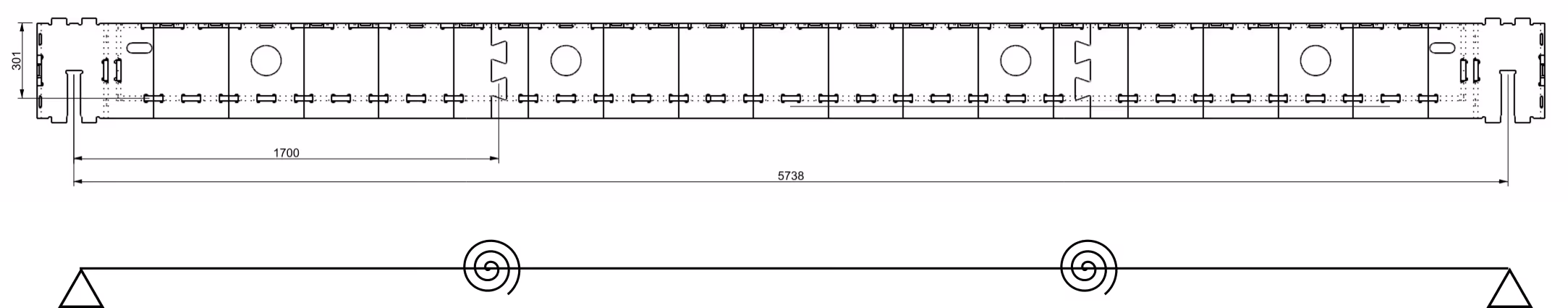
Given the span, a L beam is chosen. The L beam spans across 5738 mm (centre-column to centre-column), and it can be modelled as an Euler-Bernoulli beam element with rotational springs in correspondence of the castellated joints (see Figure below). The beam can be considered simply supported.
For a L beam, the following values are taken according to the engineering guidelines:
- \(W_{L/2}=1135296\,mm^3\)
- \(W_{j}=1135296\,mm^3\)
- \(I=28765\,cm^4\)
- \(k_r=2295\,kNm\)
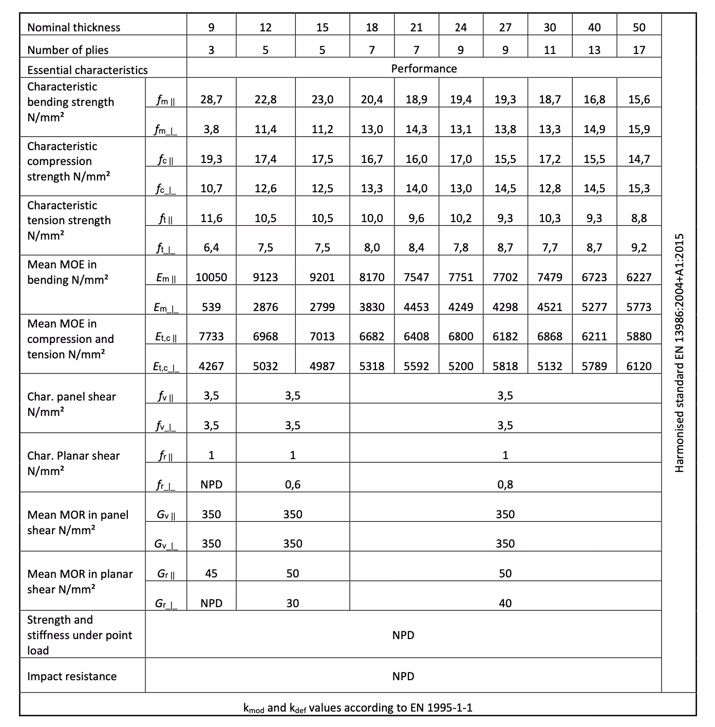
It is assumed that beams are made of WISA plywood, which properties are reported in the Figure below.
Load definition
The permanent load \(G_{beam}\) acting on the beam can be calculated according to the equation below:
\(G_{beam}= \overbrace{SW_{beam}}^{0.16 kN/m}+\overbrace{G_{imposed}}^{0.5 kN/m^2} \cdot \overbrace{i_{beams}}^{0.6m}=0.46 kN/m\)
where \(SW_{beam}\) is the self-weight of the beams, \(G_{imposed}\) is the super imposed load and \(i_{beams}\) is the inter-axis between the beams. An arbitrary super imposed load equal to \(0.5\, kN/m^2\) is considered for the sake of this worked example.
According to Eurocode 1, the imposed load \(IL)\) for residential category is recommended to be taken equal to 2 kN/m\(^2\). Hence, the linear live load on the beam \(Q_{beam}\) is equal to:
\(Q_{beam}= \overbrace{IL}^{2 kN/m^2} \cdot \overbrace{i_{beams}}^{0.6m}=1.2 kN/m\)
Serviceability limit state (SLS)
At the serviceability limit state (SLS), it is checked that: 1) the maximum elastic deflection under the frequent load combination is lower than a threshold of L/250 (with L the span), and 2) and the long term deflection under the quasi permanent load combination is lower than a threshold of L/250.
The value of \(q_{fr}\) (frequent) and \(q_{qp}\) are calculated as:
\(q_{fr} =\overbrace{G_{beams}}^{0.46}+\overbrace{\psi_2}^{0.7}\overbrace{Q_{beams}}^{1.2}=1.3\,kN/m\)
\(q_{qp} =\overbrace{G_{beams}}^{0.46}+\overbrace{\psi_2}^{0.3}\overbrace{Q_{beams}}^{1.2}=0.82\,kN/m\)
The maximum vertical displacement \(v_{max}\) of the beam in the midspan can be calculated as:
\(v_{max}=\frac{5qL^4}{384EI}+\frac{qa^2}{2k_r}[L-a]\)
where \(E\) is the elastic modulus of timber, \(I\) is the effective second moment of inertia, \(a\) is the distance between the castellated joint and the support, \(L\) is the span and \(k_r\) is the rotational stiffness of the joint.
The check on the maximum elastic deflection is reported below:
\(d_{el}=\frac{5\overbrace{q_{fr}}^{1.3}\overbrace{L}^{5738} \,^4}{384\underbrace{E}_{8170}\underbrace{I}_{28765\cdot10^{4}}}+\frac{\overbrace{q_{fr}}^{1.6}\overbrace{a}^{1700}\,^2}{2\underbrace{k_r}_{2295\cdot10^{6}}}[L-a]=11.1\,mm \le\frac{L}{250} \,\checkmark\)
A check on the long term deflection \(d_{lt}\) is reported below. Note that it is assumed that the beams are working in Service Class I, defined by Eurocode 5 as: characterized by a moisture content in the material corresponding to a temperature of 20 C and the relative humidity of the surrounding air only exceeding 65% for a few weeks per year.
\(d_{lt}=[\frac{5\overbrace{q_{qp}}^{1.12}\overbrace{L}^{5738} \,^4}{384\underbrace{E}_{8170}\underbrace{I}_{28765\cdot10^{4}}}+\frac{\overbrace{q_{qp}}^{1.12}\overbrace{a}^{1700}\,^2}{2\underbrace{k_r}_{2295\cdot10^{6}}}(L-a)](1+\overbrace{k_{def}}^{0.8})=12.6\,mm \le\frac{L}{250} \,\checkmark\)
Ultimate limit state (ULS)
At the ultimate limit state (ULS), it is checked that the capacity of the beams is greater than the demand. Specifically, this check is carried out for the permanent loads (quasi static combination) and for the short term loads (rare combination). The rare load combination is reported below:
\(q_{ra} =\overbrace{\gamma_G}^{1.35}\overbrace{G_{beams}}^{0.46}+\overbrace{\gamma_Q}^{1.5}\overbrace{Q_{beams}}^{1.2}=2.42\,kN/m\)
Mid-span check
The value of the maximum bending moment for permanent loads \(M_{Sd,qp,L/2}\) and value of the maximum bending moment for short term loads \(M_{Sd,ra,L/2}\) are reported below:
\(M_{Sd,qp,L/2}=\frac{\overbrace{q_{qp}}^{0.82}\overbrace{L}^{5738} \,^2}{8}=3.4\,kNm\)
\(M_{Sd,ra,L/2}=\frac{\overbrace{q_{ra}}^{2.42}\overbrace{L}^{5738} \,^2}{8}=10.0\,kNm\)
The moment capacity \(M_{Rd,L/2}\) in the mid-span of the beams is calculated as:
\(M_{Rd,L/2}=\overbrace{W_{L/2}}^{1135296\cdot 10^{-6}}\cdot \overbrace{f_{c,0}}^{16.7}=18.9\,kNm\)
The checks are reported in the equations below. Note that the resisting bending moment at permanent loads is indicated with \(M_{Rd,p,L/2}\), and the resisting bending moment at instantaneous loads is indicated with \(M_{Rd,st,L/2}\).
\(M_{Rd,p,L/2}=\frac{\overbrace{k_{mod}}^{0.6}\overbrace{M_{Rd,L/2}}^{18.9} }{\underbrace{\gamma_M}_{1.25}}=9.0\,kNm\ge M_{Sd,qp,L/2} \, \checkmark\)
\(M_{Rd,st,L/2}=\frac{\overbrace{k_{mod}}^{1.1}\overbrace{M_{Rd,L/2}}^{18.9} }{\underbrace{\gamma_M}_{1.25}}=16.6\,kNm\ge M_{Sd,ra,L/2} \, \checkmark\)
Dovetail joint check
The value of the maximum bending moment for permanent loads \(M_{Sd,qp}\) and value of the maximum bending moment for short term loads \(M_{Sd,ra}\) at the joint are reported below:
\(M_{Sd,qp,j}=\frac{4\overbrace{a}^{1700}(\overbrace{L-a}^{5738-1700})}{\underbrace{L^2}_{5738^2}}M_{Sd,qp,L2}=0.83M_{Sd,qp,L/2}=2.35\,kNm\)
\(M_{Sd,ra,j}=\frac{4\overbrace{a}^{1700}(\overbrace{L-a}^{5738-1700})}{\underbrace{L^2}_{5738^2}}M_{Sd,ra,L2}=0.83M_{Sd,ra,L/2}=8.3\,kNm\)
The moment capacity \(M_{Rd,j}\) at the joint is calculated as:
\(M_{Rd,j}=\overbrace{W_{j}}^{1135296\cdot 10^{-6}}\cdot \overbrace{f_{c,0}}^{16.7}=18.9\,kNm\)
The checks are reported in the equations below. Note that the resisting bending moment at permanent loads is indicated with \(M_{Rd,p,j}\), and the resisting bending moment at instantaneous loads is indicated with \(M_{Rd,st,j}\).
\(M_{Rd,p,j}=\frac{\overbrace{k_{mod}}^{0.6}\overbrace{M_{Rd,j}}^{18.9} }{\underbrace{\gamma_M}_{1.25}}=9.0\,kNm\ge M_{Sd,qp,j} \, \checkmark\)
\(M_{Rd,st}=\frac{\overbrace{k_{mod}}^{1.1}\overbrace{M_{Rd,j}}^{18.9} }{\underbrace{\gamma_M}_{1.25}}=16.6\,kNm\ge M_{Sd,ra,j} \, \checkmark\)
Column check
The axial demand for permanent loads \(N_{Sd,qp}\) and the axial demand for short term loads \(N_{Sd,ra}\) is equal to:
\(N_{Sd,qp}=\frac{\overbrace{q_{qp}}^{0.82}\overbrace{L}^{5738}}{2}=2.4\,kN\)
\(N_{Sd,ra}=\frac{\overbrace{q_{ra}}^{2.42}\overbrace{L}^{5738}}{2}=6.9\,kN\)
The value of \(N_{rd}\) for a 2.7 m column is equal to 101.6 kN as per engineering guidelines. Therefore:
\(N_{Rd,p}=\frac{\overbrace{k_{mod}}^{0.6}\overbrace{N_{Rd}}^{101.6} }{\underbrace{\gamma_M}_{1.25}}=48.8\,kN\ge N_{Sd,qp} \, \checkmark\)
\(N_{Rd,st}=\frac{\overbrace{k_{mod}}^{1.1}\overbrace{N_{Rd}}^{101.6} }{\underbrace{\gamma_M}_{1.25}}=89.4\,kN\ge N_{Sd,ra} \, \checkmark\)
.svg)

