WikiHouse
Design of a floor for lateral loads
How do Skylark floors deal with lateral loads?
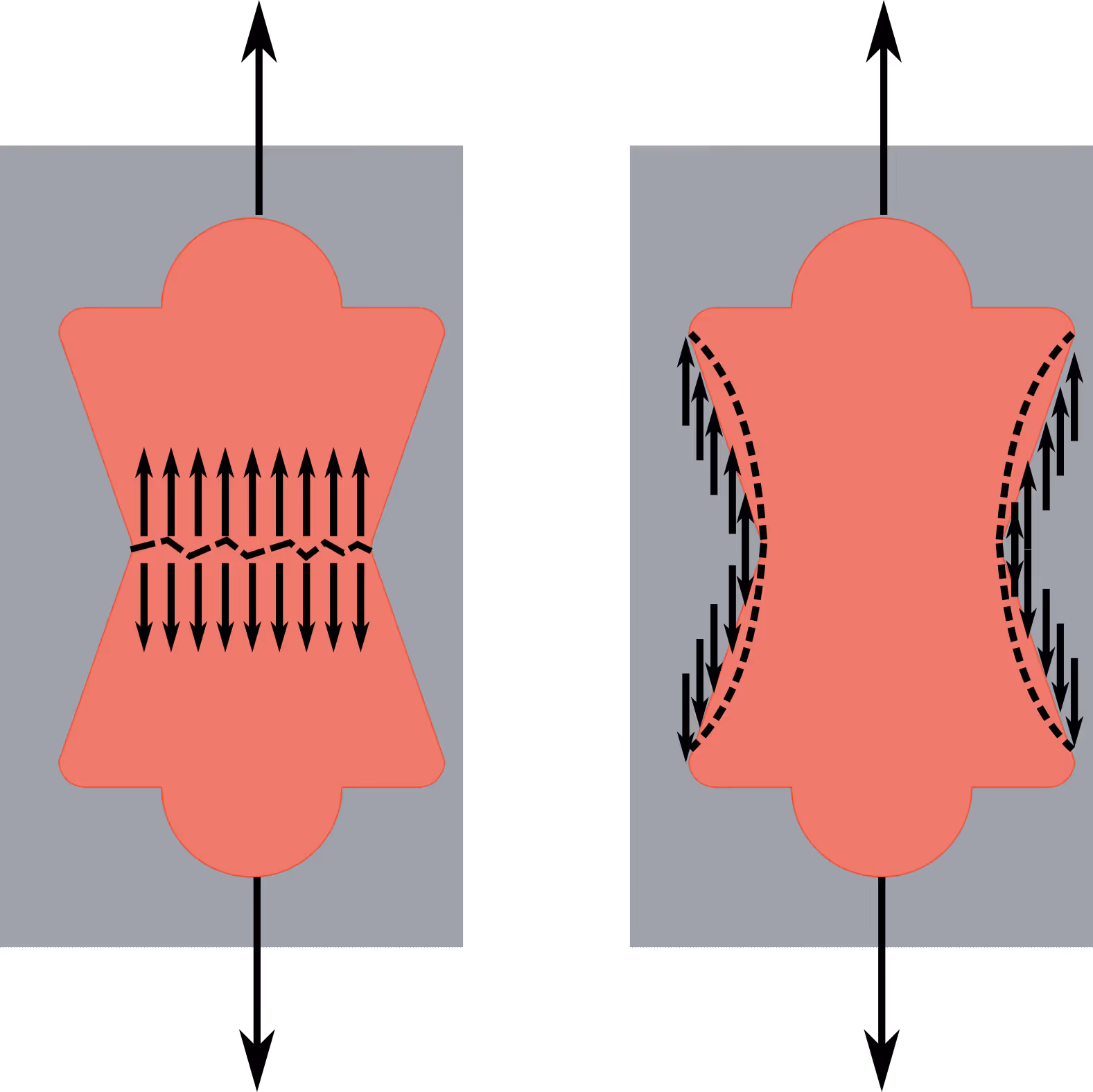
Skylark floors transfer lateral loads such as wind and earthquakes into the shear walls. It is important to make sure that the floor (also called diaphragm) has enough capacity to transfer such loads. If the load is parallel to the longitudinal axis of the beams, this means checking the floor bow ties for tension and shear.
A design example according to the Eurocodes is shown below.
Worked example
A Skylark floor made by 6 XS beams, 12 L beams and 2 end beams is subjected to lateral wind pressure equal to \(q\) = 4kN/m (UltimateLimit State). Verify that the diaphragm satisfies the design criteria according to the Eurocodes.
Geometry
The geometry of the diaphragm is shown in the figure below. The floor is made up of 18 beams and two end beams, for a total footprint of 6.0 m x 11.4 m. Beams are connected together by using bow ties, which are spaced according to the figure below. The 3D model can be dowloaded from here.

The elements are made of \(w=18 mm\) thick plywood sheets. Material properties are reported in the table below.
Actions on the diaphragm
Assuming a simply supported static scheme, the diaphragm is subjected to bending moment and shear. Therefore, bow ties are subjected to both shear and tensile forces.

Three rows of bow ties are considered to find out the worst case scenario. The values of shear (V) and bending moment (M) are calculated based on the bow tie distance z from the support:
\[M(z)=-\frac{qz^2}{2}+\frac{qLz}{2}\]
\[T(z)=\frac{qL}{2}-qz\]
Given L=11.4 m and q=4kN/m, it follows:
Capacity of the Diaphragm
Capacity of the bow tie
The tensile capacity of one bow tie \(T\) is calculated as the minimum force between the tension failure \(T_t\) and the compression/shear failure \(T_c\).
\(T_t\) can be calculated as:
\(T_t=\underbrace{f_{t,0} A_t}_{12\cdot 55.7 \cdot18}=12\ kN
\)
The calculation of \(T_c\) requires the following iterative process:
1. Select an arbitrary \(T_c\), for example 1 kN.
2. Calculate the bow tie slip \(s=\frac{F_2}{k_t}\) where \(k_t\) is the bow tie stiffness in tension.
3. Calculate the contact zone between the bow tie and the panel by considering the bow tie slip.
4. Decompose \(T_c\) into \(T_{c,comp}\) (compression force) and \(T_{c,shear}\) (shear) on the contact zone.
5. Calculate the compression stress \(\sigma_C\) and \(\tau_S\) by considering the contact area.
6. Check if the element has failed according to \(\frac{\sigma_c}{f_{c,d}}+\frac{\tau_s}{f_s}=1\). If not, increase \(T_c\) until failure.
The iterative calculations are reported in the spreadsheet here. The "goal seek" function was used.
This leads to \(T=5.2 kN\). By considering \(k_{mod}=1.1\) (load duration factor for instantaneous events), this leads to \(T=5.7 kN\).
The shear capacity \(S\) of the bow tie is equal to:
\(S=\underbrace{A_s}_{55.7 \cdot 18}\overbrace{f_s}^{3.5}=3.5\ kN
\)
By considering \(k_{mod}=1.1\) (load duration factor for instantaneous events), this leads to \(S=3.85 kN\).
Shear capacity of the diaphragm
The shear capacity \(V_{rd}\) of the diaphragm can be calculated as:
\(V_{rd}=nS\)
where \(n\) is the number of bow ties and \(S\) is the shear capacity of the bow tie.
It follows that:
\[V_{rd,1}=V_{rd,2}=\frac{\overbrace{n}^{12}\overbrace{S}^{3.85}}{\underbrace{\gamma}_{1.2}}=38.5\ kN\]
\[V_{rd,3}=\frac{\overbrace{n}^{18}\overbrace{S}^{3.85}}{\underbrace{\gamma}_{1.2}}=57.8\ kN\]
Moment capacity of the diaphragm
The moment capacity \(M_{rd}\) of the diaphragm can be calculated as:
\[M_{rd}=\frac{\sum_i^{n}d_iT_i}{\gamma}\]
where \(n\) is the number of bow ties, \(T_i\) is the tensile capacity of the \(i^{th}\) bow tie, \(d_i\) is the distance of the \(i^{th}\) bow tie from the pivoting point and \(\gamma\) is the safety factor.
The easiest way is to build a spreadsheet similar to this one. This leads to:

This leads to:
\[M_{rd,1}=M_{rd,2}=\frac{\sum_i^{12}\overbrace{d_iT_i}^{86.58}}{\underbrace{\gamma}_{1.2}}=72.2\ kNm\]

This leads to:
\[M_{rd,1}=M_{rd,2}=\frac{\sum_i^{12}\overbrace{d_iT_i}^{86.5
This leads to:
\[M_{rd,3}=\frac{\sum_i^{18}\overbrace{d_iT_i}^{191.5}}{\underbrace{\gamma}_{1.2}}=159.6\ kNm\]
Capacity check
It is verified that:
\[\frac{\overbrace{V_{sd,1}}^{21.6}}{\underbrace{V_{rd,1}}_{38.5}}+\frac{\overbrace{M_{sd,1}}^{7}}{\underbrace{M_{rd,1}}_{72.2}}=0.67\le1\ \checkmark\]
\[\frac{\overbrace{V_{sd,2}}^{7.2}}{\underbrace{V_{rd,2}}_{38.5}}+\frac{\overbrace{M_{sd,2}}^{58.9}}{\underbrace{M_{rd,2}}_{72.2}}=1.0\le1\ \checkmark\]
\[\frac{\overbrace{V_{sd,3}}^{0}}{\underbrace{V_{rd,3}}_{38.5}}+\frac{\overbrace{M_{sd,3}}^{65.4}}{\underbrace{M_{rd,3}}_{191.5}}=0.34\le1\ \checkmark\]
Finite element model
An elastic finite element model was developed in Karamba3D to check the results. The diaphragm was modelled by using a shell element with thickness equal to 18 mm. Bow ties were modelled with a single elastic spring having \(k_t=\ 1.5\ kN/mm\) and \(k_s=3\ kN/mm\). The model is available here for download.
To check the calculation of \(M_{rd}\), the diaphragm is loaded by a distributed wind load \(q_{rd}\) proportional to the moment capacity.
case 1
Considering \(q_{rd,2}\):
\(q_{rd,2}=\frac{\overbrace{M_{rd,2}}^{86.6}}{\underbrace{M_{sd,2}}_{58.9}}\cdot \overbrace{q_{sd}}^{4}=5.9\ kN/m\)
leads to a tensile force equal to 5.5 kN in the \(12^{th}\) bow tie in row 2. Results are consistent with the analytical model.

case 2
Considering \(q_{rd,3}\):
\[q_{rd,3}=\frac{\overbrace{M_{rd,2}}^{191.5}}{\underbrace{M_{sd,2}}_{65.4}}\cdot \overbrace{q_{sd}}^{4}=11.7\ kN/m\]
leads to a tensile force equal to 5.5 kN in the \(18^{th}\) bow tie in row 3. Results are consistent with the analytical model.
.svg)

