WikiHouse
Design of shear walls for lateral loads
How does Skylark deal with lateral loads?
Skylark walls are the main structural elements resisting lateral loads such as earthquakes and wind. The structural checks need to verify the following:
- That the wall is stiff enough to limit the inter-storey lateral deformation within code limits.
- That the wall is strong enough to resits lateral loads.
The key parameters governing the performance of the walls are:
- Aspect ratio of the wall, e.g., squatter walls are stronger and stiffer than slender ones.
- Strength and stiffness of the bow ties.
A design example according to the Eurocodes is reported below.
Worked example
A Skylark wall made by four S columns and two S corners is subjected to lateral load equal to \(F_{SLS}\) = 40kN at the Serviceability Limit State, and to lateral load equal to \(F_{ULS}\) = 60kN at the UltimateLimit State. Verify that the wall satisfies the design criteria according to the Eurocodes.
Geometry
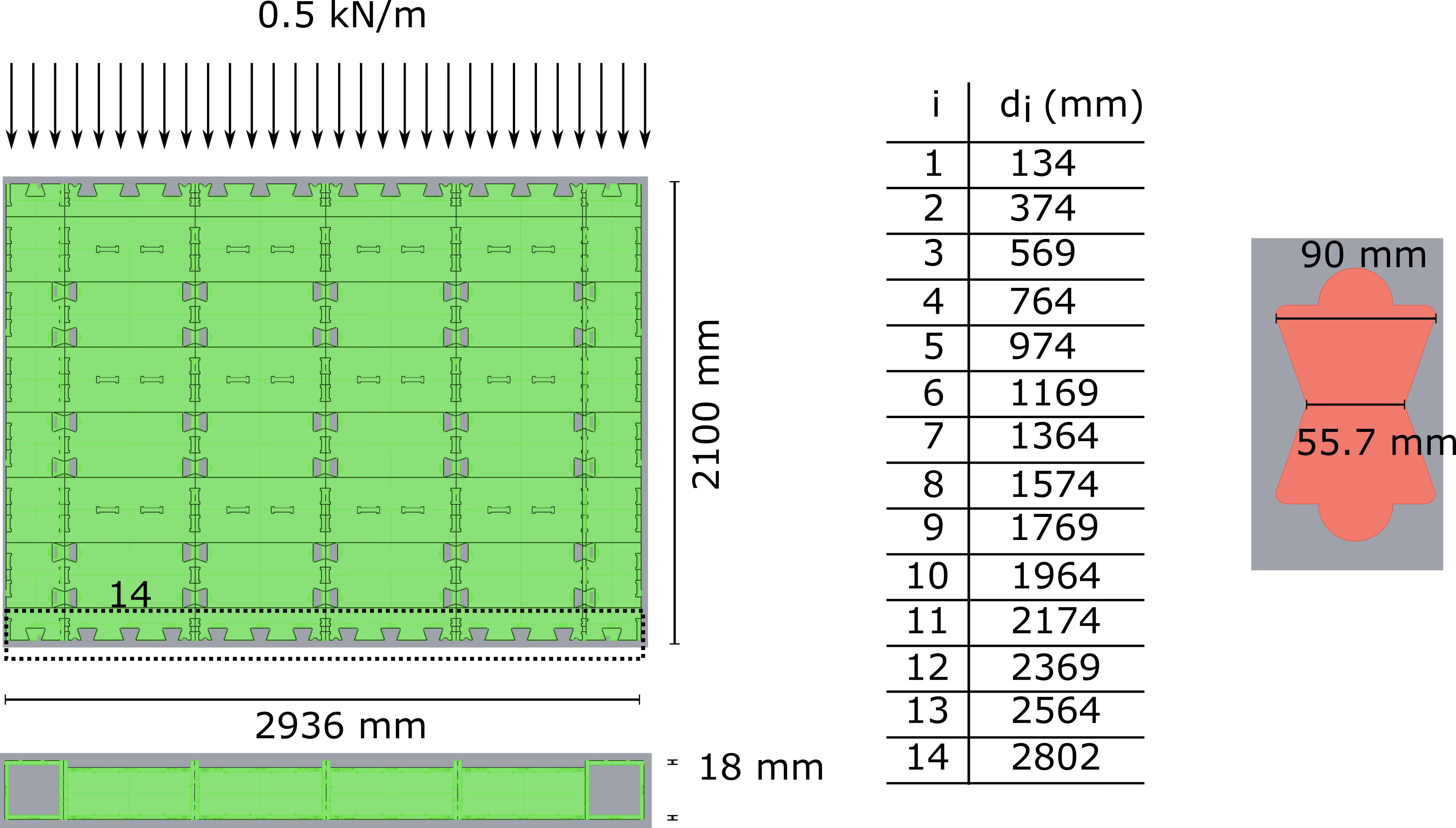
The wall is 2936 mm wide and 2100 mm high, and subjected to a distributed vertical load equal to 0.5 kN/m. There are 14 bow ties on each side providing shear capacity and moment capacity. The shear stiffness and tensile stiffness of one bow tie are equal to \(k_s=3kN/mm\) and \(k_t=1.5kN/mm\), respectively.
The elements are made of \(w=18 mm\) thick plywood sheets. Material properties are reported in the table below.
Serviceability Limit State (SLS)
The SLS is verified if the lateral displacement of the wall \(\Delta_{tot}\) subjected to the lateral load \(F_{SLS}\) is less than \(\frac{h}{300}\) =7 mm.
The total displacement \(\Delta_{tot}\) is equal to:
\(\Delta_{tot}=\underbrace{\Delta_T}_{Translation}+\underbrace{\Delta_S}_{Shear}+\underbrace{\Delta_R}_{Rocking}\)
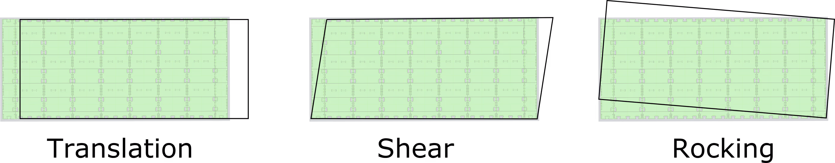
The term \(\Delta_T\) can be calculated as:
\(\Delta_T=\frac{F}{2nk_s}\)
where \(n\) is the number of bow ties and \(k_s\) the shear stiffness of the bow ties. The factor 2 appears because bow ties are placed on both faces of the wall. Hence:
\( \Delta_T=\frac{\overbrace{F}^{40}}{2\underbrace{n}_{14}\underbrace{k_s}}_3=0.48\ mm\)
The term \(\Delta_S\) can be calculated as:
\(\Delta_S=\frac{Fh}{GA_s}=\frac{Fh}{2Gwt}\)
where \(G\) is the shear modulus and \(A_s=2wt\) is the shear area. Hence:
\(\Delta_S=\frac{\overbrace{Fh}^{40000\cdot2100}}{2\underbrace{Gwt}_{350 \cdot 2936 \cdot 18}}=2.27 \ mm\)
The term \(\Delta_R\) can be calculated as:
\(\Delta_R=\frac{Fh-\frac{qw^2}{2}}{2k_t\sum_1^{n} d_i^2}\cdot h\)
where \(k_t\) is the tensile stiffness on the bow tie, and \(d_i\) the distance of each bow tie from the wall edge. Hence:
\(\Delta_R=\frac{\overbrace{Fh}^{40000\cdot2100}-\frac{\overbrace{qw^2}^{0.5\cdot2936^2}}{2}}{2\underbrace{k_t}_{1.5\cdot 10^3}\underbrace{\sum_1^{n_h} d_i^2}_{39.5 \cdot10^6}}\cdot \overbrace{h}^{2100}=1.45\ mm\)
Therefore:
\(\Delta_{tot}=4.2 \ mm \le 7 \ mm \ \checkmark\)
A spreadsheet with the calculations is available here.
Ultimate Limit State (ULS)
The capacity \(C\) of the wall is the minimum between the horizontal shear capacity \(F_H\) and the overturning capacity \(F_R\):
\(C=min(F_R,F_H)\)
The term \(F_S\) can be calculated as:
\( F_S=2nS\)
where \(S\) is the shear capacity of the bow tie. The factor 2 appears because there are \(n\) bow ties on each face of the wall.
The term \(F_R\) can be calculated as:
\(F_R= \left( \frac{2\sum_1^{n}d_i^2}{d_n}T+ \frac{qw^2}{2} \right) \cdot \frac{1}{h}\)
where \(T\) is the tensile capacity of the bow tie.
Capacity of the bow tie
The tensile capacity of one bow tie \(T\) is calculated as the minimum force between the tension failure \(T_t\) and the compression/shear failure \(T_c\).
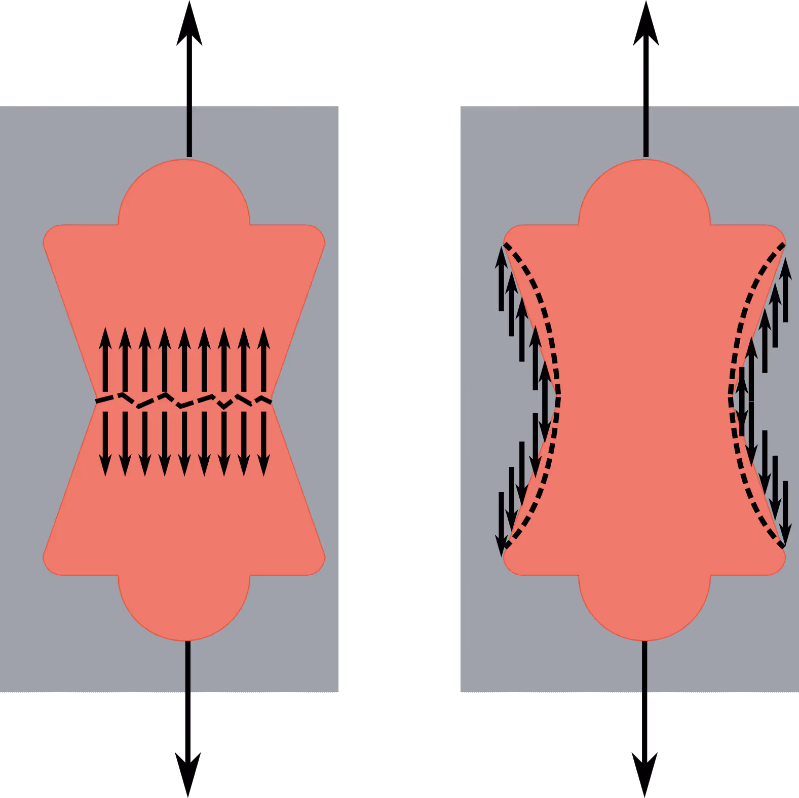
\(T_t\) can be calculated as:
\(T_t=\underbrace{f_{t,0} A_t}_{12\cdot 55.7 \cdot18}=12\ kN
\)
The calculation of \(T_c\) requires the following iterative process:
1. Select an arbitrary \(T_c\), for example 1 kN.
- Calculate the bow tie slip \(s=\frac{F_2}{k_t}\) where \(k_t\) is the bow tie stiffness in tension.
- Calculate the contact zone between the bow tie and the panel considering the bow tie slip.
- Decompose \(T_c\) into \(T_{c,comp}\) (compression force) and \(T_{c,shear}\) (shear) on the contact zone.
- Calculate the compression stress \(\sigma_C\) and \(\tau_S\) by considering the contact area.
- Check if the element has failed according to \(\frac{\sigma_c}{f_{c,d}}+\frac{\tau_s}{f_s}=1\). If not, increased \(T_c\) until failure.
The iterative calculations are reported in the spreadsheet here. The "goal seek" function was used.
This leads to \(T=5.2 kN\). By considering \(k_{mod}=1.1\) (load duration factor for instantaneous events), this leads to \(T=5.7 kN\).
The shear capacity \(S\) of a bow tie is equal to:
\(S=\underbrace{A_s}_{55.7 \cdot 18}\overbrace{f_s}^{3.5}=3.5\ kN
\)
By considering \(k_{mod}=1.1\) (load duration factor for instantaneous events), this leads to \(S=3.85 kN\).
Capacity of the wall
The shear capacity of the wall can be calculated as:
\(F_S=2nS=107.8\ kN\)
Considering a safety coefficient equal to 1.2 leads to \(F_S=89.8 kN\).
The rocking capacity \(F_R\) is equal to:
\(F_R= \left( \frac{2\overbrace{\sum_1^{n}d_i^2}^{39.5\cdot 10^6}}{\underbrace{d_n}_{2802}}\underbrace{T}_{5700}+ \overbrace{\frac{qw^2}{2}}^{0.5 \cdot 2936^2} \right) \cdot \underbrace{\frac{1}{h}}_{2100}=77.5\ kN\)
Considering a safety coefficient equal to 1.2 leads to \(F_R=64.6 kN\).
Therefore:
\(C=min(F_S,F_R)=min(89.8,64.6)=64.6\ kN \ge 60\ kN\ \checkmark
\)
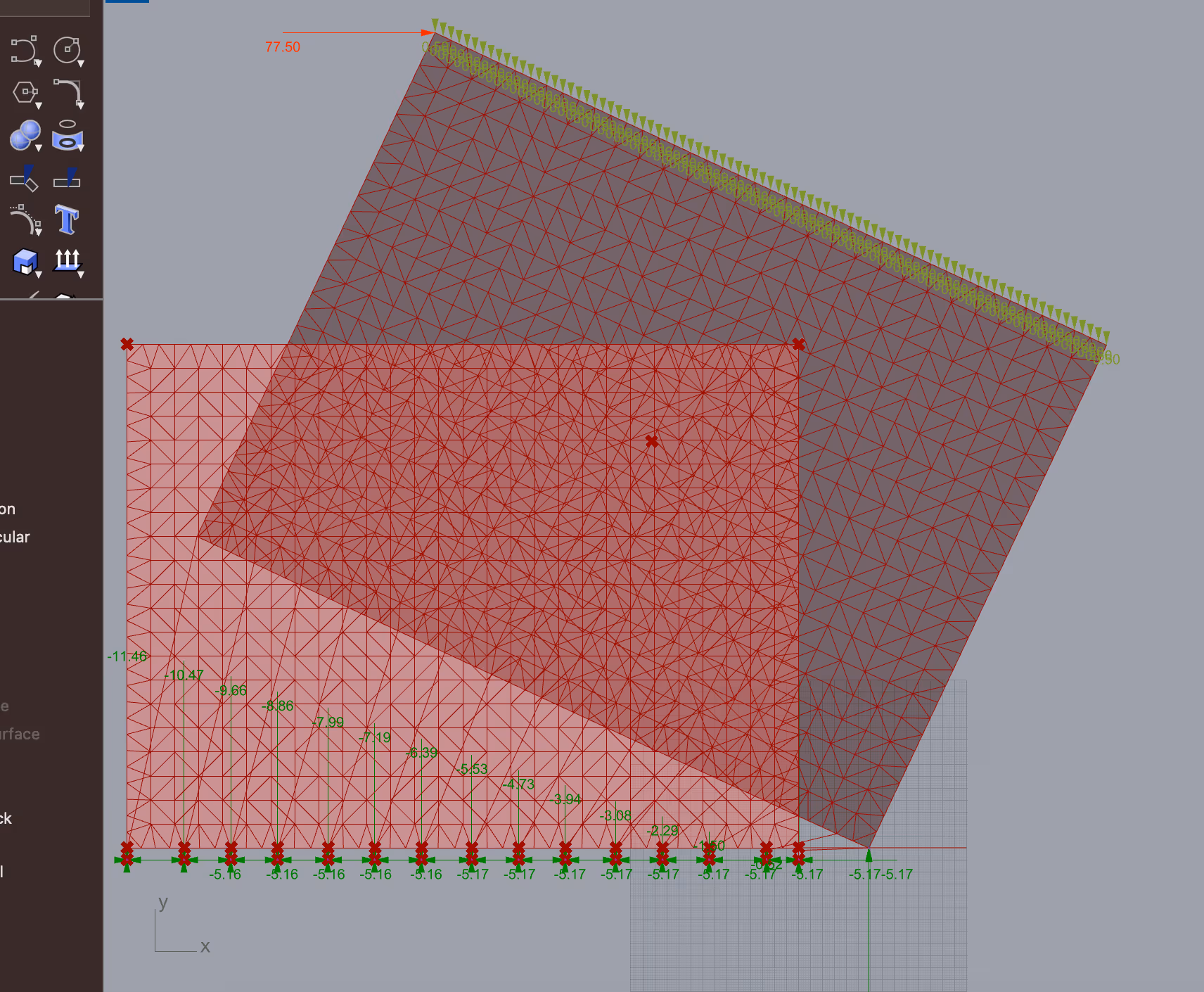
Finite element model
An elastic finite element model was developed in Karamba3D to check the results. The wall was modelled by using a shell element with thickness equal to 36 mm. Bow tie couples (one each side) were modelled with a single elastic spring having \(k_t=\ 3kN/mm\) and \(k_s=6\ kN/mm\), i.e., double the value of a single bow tie. The model is available here for download.
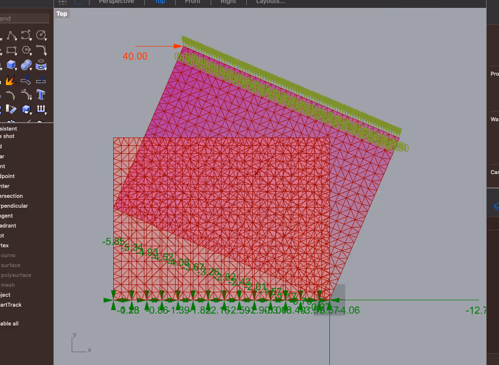
The wall was subjected to a lateral load equal to 40 kN . It can be seen that the force \(T_{14}\) in the \(14^{th}\) bow tie couple is equal to \(T_n=5.85\ kN\). This leads to a vertical uplift equal to:
\(\Delta_n=\frac{\overbrace{T_n}^{5.85}}{\underbrace{k_t}_{3}}=1.95\ mm\)
Hence:
\( \Delta_R=\frac{\overbrace{\Delta_n}^{1.95}}{\underbrace{d_n}_{2802}} \cdot \overbrace{h}^{2100}=1.46\ mm \)
which is very close (0.01 mm) to the value reported by the analytical model.
For a lateral load equal to \(77.5 kN\), it can be seen that the force in the \(14^{th}\) bow tie couple is equal to \(2T=11.5kN\). This leads to a force \(T=5.75\) which is only 0.05 kN different from the values calculated by using the analytical model.
.svg)

